Wheel robot
To build a wheel robot, use the mechancial parts and materials from the obsolete and scrap PC computer peripherals and equipment.

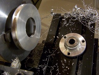
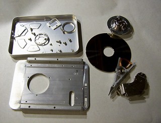
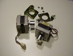
There are many useful parts in a PC computer equipment, such as floppy drives, hard drives, printers, and etc. These mechanical parts can be used for projects and experiments. Most of the components are removed from the equipment that still function. Many of the parts will not fit well completely in the project, but most of them can be easily modified.

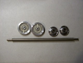
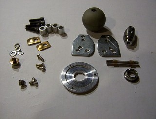
In this project, to build a 3-wheel robot, the parts and materials are collected for suitable dimensions and shapes so that they can be modified according to the project design. I have salvaged a lot of parts from computer equipment to build a robot.


Loading ....


robot
View larger image

w-robot
Part 1 - Mechancial parts and assembly
Parts for driving wheels and axial
wheel-parts
First, start with the driving wheels. Two spindle pulleys are removed from two 5.25" Shugart floppy drives, and two spindle hubs with bearings are taken from another 5.25" floppy drives. A paper roller shaft is removed from an HP LaserJet printer.


wheel-mod

axial
The spindle pulleys will be used as driving wheels for the robot. They need to be modified by boring a larger hole at the center so the bearing hub can fit into it. The rim face is cut with a V-grove about 0.125" deep for holding an o-ring as a tire.


Cut a piece of a suitable length from the paper roller shaft for the wheel axial. The diameter on both ends should be turned to a smaller size using the lathe, so the bearings can be mounted onto it. The center section is milled flat at about 0.05" depth and tapped with two #6-32 threaded hole for mounting onto the frame. 
Wheel assembly
o-ringgearThe two rubber o-rings can to be used for the tires, but they are not removed from any PC equipment. They are the only major mechancial parts bought from a surplus hardware store.

Two sets of laser printer plastic gears are used, the larger gears are mounted on the driving wheels. The smaller gears are mounted on the motors' shafts. The two sets of gears are engaged together for the motors to drive the wheels..
axial-wheelaxial-assemblyThe two larger gears need to be modified to bore a larger center hole and drilled with three 0.125" holes for mounting on the bearing hub and the spindle pulley.


The driving wheel axial assembly.


Click on the image to View larger size.
Support base
seagate hd-castingThis is the Seagate ST31276A hard drive housing. The hard drive mounting plate is made of cast aluminum and with a thick support. The robot base will use this hard drive mounting plate. 
base The seagate hard disk housing plate is finished with the surface cleaned up by a milling machine, and drilled the necessary holes for mounting all the components.    
Caster wheel parts and assembly
caster-materials The parts and materials needed for making the caster wheel are: a leftover laser printer paper roller shaft, which part of it is used for the wheel axial, two pieces of laser printer hardware, a 5.25" floppy drive spindle hardware, a floppy drive spindle flange bearing, a CD-ROM drive laser head sliding pin with 2 brass brushings, and a mouse ball.

The mouse ball is drilled with a hole through the center, the two ends are counter bored with the diameter equalling to the size of the brass brushing with about 0.1" depth (about the same length of the brass brushing). The drill through center diameter is slightly larger than the diameter of the sliding pin.

The shaft and the bearing are used for making the swivel joint of the caster wheel.

ball-drill caster-parts Drilling a center hole on a round steel ball will be quite difficut, so I find it easier to  drill it on the lathe.


This is the complete set of modified parts for the assembly of the caster wheel.
caster-wheel
Viiew larger image

This is the finished caster wheel assembly. The CD-ROM laser head sliding pin and the two brass brushings are inserted into the drill hole on the center of the mouse ball as a wheel axial.


Motors
motorTwo stepper motors were removed from two 5.25" floppy drives. The specification for the motor is a 12V, 5-wire, 3.6o per step unipolar drive. The motor shaft comes with a pulley attached to it  that needs to be modified for mounting the smaller plastic gear. 
A complete mechancial assembly
wheel-robot
View larger image
front
View larger image
back
View larger image
bottom
View larger image

Test all the wheels so they can move smoothly. Next step is the installation of a controller for test drive.


homehome backreturn nextnext