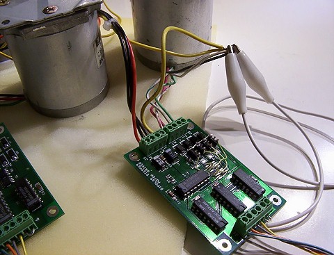
Stepper motor driver

Bipolar 
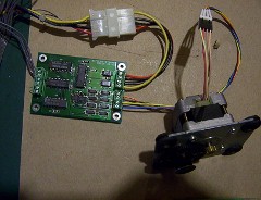
stepper motor driver board: this circuit board is used for driving a single small power stepper motor. The driver board can be connected to a stepper motor with a 3-5V power supply to 
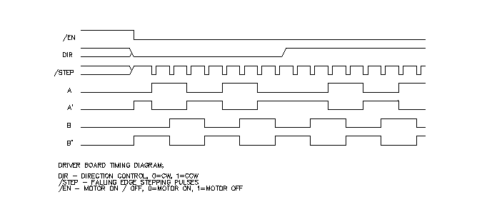
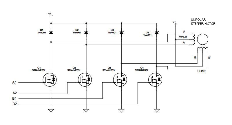
a maximum of 2.5A current.


assembly


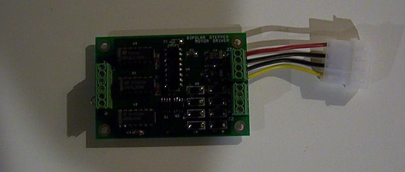
The Diode Inc. ZXMHC3F381N8 H-bridge MOSFET transistors are used in the circuit to drive the stepper motor windings, it is a  complementary array containing 4 transistors to form an H-bridge. The advantage of using MOSFET is that this device is simpler to interface with the logic circuit. Unlike the bi-polar transistor, it is controlled by a gate voltage and the gate power is only drawn at the transistion time. It consumes almost no gate power to maintain the device at the ON state, thus the heat dissipation on the device will be less. But the MOSFET requires a stronger pull up and pull down power to turn the channels ON and OFF. The interfacing logic devices to the gate terminals should use 74HCT, 74HC, and etc. series devices. Since this MOSFET's gate threadhold voltage is 3V, the LVTTL (3.3V logic) should not be used to drive the transistors.

drivers
bpolar-waveform

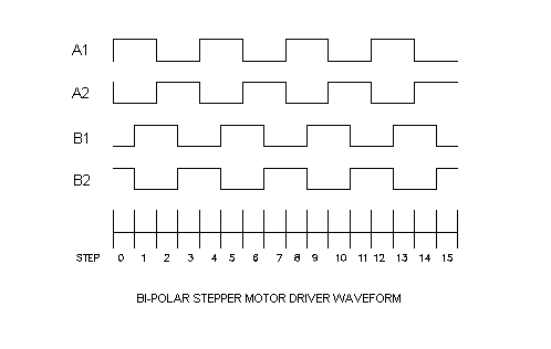
In the 2-coil, bi-polar stepper motor, the driving pulses require 4-phase signals. The A terminal is always inverted to A' terminal, same as the B-B' terminals. The B-B' pulse phases are 90o  lagging when it turns in a clockwise direction and 90o leading at a counter-clockwise direction.


The driver schematic contains 2 major input signals from the controller. The direction control (DIR) commands the rotor in turning clockwise or counter-clockwise. The step pulse control (/STEP, inverted logic) turns the stepper motor one step ahead. The driver board circuit U2, 74LS93 , a binary counter, a 74LS74 D-FF, U3, and a 74HCT157 2-1 multiplexor decodes the DIR and STEP signals and generates the sequence of 4-phase stepping pulses. 

Some controllers provide a signal to control the motor ON/OFF, the /EN is lower active input signal (0=ON). The /EN input needs to be connected to GROUND when it is not used.


timing


scanjet motorTesting on a Hewlett-Packard (HP) ScanJet stepper motor, which is a 5V supply bipolar stepper motor, there is not much information that can be found about the specifications for this motor. The only markings on the label is the part number: STH-39D1126, and that it has a 4.1 ohm coil resistance and 1.8 degree/step.

The motor's wiring terminals connect to the driver board:
A - YELLOW
A' - RED
B - BROWN
B' - ORANGE


HP III motors

Testing the driver board in LinuxCNC 2.5


The Driver boards are being tested in LinuxCNC with 3-axis example G-code.
Three HP LaserJet III printers' stepper motors are connected to the driver boards which are driven by the lp0 (LPT1). The HP LaserJet III printer stepper motor is 5.1V rated unipolar stepper motors. This motor can be wired in a bipolar mode with the winding's center tap terminals not being used, and the rated supply voltage is 7 volts. However, in the test, it is operating in a bipolar mode and the power supply of 5V is used.

The HP LaserJet III stepper motor's wiring terminals connect to the driver board in bipolar configuration;
A - GREEN
A' - WHITE / GREEN
B - RED
B' - WHITE / RED

The BLACK and WHITE terminals are no connections.


Since there is the same waveform to drive the  bipolar stepper motors and the unipolar stepper motors in full step mode. The same circuit can be modified to drive the unipolar stepper motors by replacing the H-bridge MOSFET. The modified circuit is relatively simpler since it only needs four N-channel MOSFET transistors The connections to the logic has a slight difference. Although the circuit does not support wave driving and half-step driving modes, the full step driving has the maximum torque size efficency and gives less vibration. This unipolar driver can operate at higher voltage supply, it supports up to 12V 3A motors.
unipolar driver


HPIII-motors2
The driver board is modified by replacing the two H-bridge MOSFETs with four N-MOSFETs. The HP LaserJet III stepper motor is wired in unipolar mode. The BLACK and WHITE terminals are connecting to the +5V power supply. 


bi-polar

Bipolar stepper motor driver schematic
Download (PDF file)


bi-polar

Unipolar stepper motor driver schematic
Download (PDF file)


Back