|
To
build
a stepper
motor tester, the circuit contains two sets of drivers that can support
both unipolar and bipolar stepper motors. The control circuit
and
driver circuit are in separate power supplies that can work on a wider
range of different power supplies of motors.
The motor
driver can support motors with power supplies from 5V-24V.
 The
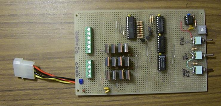
stepper tester contains three major sections: the clock
generator, phase sequence of waveform logic, and power transistor
drivers. The 3 switches are used in the circuit for
the selection of forwards / backwards
movement, motor start-and-stop control, and a wave / full step drives.
The tester does not provide a half-step drive.
 The
oscillator circuit is using a NE555 to wire as astable
multivibrator. The frequency can be adjusted from approximately
7
Hz to 267 Hz. The
oscillator circuit is using a NE555 to wire as astable
multivibrator. The frequency can be adjusted from approximately
7
Hz to 267 Hz. For instance, a 3.6 degree/step- stepper motor will have about 4.2 RPM to 160 RPM. So a 1.8 degree/step-stepper motor will have half of the rotating speed. In the circuit
diagram, the clock signal from the oscillator connects to the 74LS193, an up/down binary counter. When the clock signal
connects to the count-up input,
it will generate the pulse sequence to the stepper motor in a
clockwise direction. It will turn counter-clockwise if the
count-down input is used. The 74LS139 decodes the two-bit counter
output and generate the 4-phase pulses to drive the stepper motors
in the 4-phase terminals respectively.
 Driving
the unipolar and bipolar stepper motors are the same, but each
phase will pulse alternatively. There are three methods used to
drive, but the wave drive is the simplest way: a pulse is applied to
each
of the coil terminal at a time.
 The full-step drive is similar,
but 2 coils are energized at the same time. This method will create
more torque.
 The half-step applies pulses to
one or two coils alternatively. This will create finer movements. The
half-step drive will have double the amount of steps / revolution. As
the
torque is unequal in each step, it will cause more vibration.
 The unipolar driving circuit is relatively simpler than the bipolar driver. In the diagram, four Darlington NPN transistors are used to drive each coil terminal. Only 1 transistor is turned on at a time in a wave drive. In a full-step drive, it will always have 2 transistors turned on.
In the bipolar driver diagram, four Darlington NPN power
transistors form an
H-bridge circuit to drive each coil in the bipolar stepper
motor. Two
H-bridge drivers
are needed for the four-wired bipolar stepper motor. Because the
control
circuit uses 5V (VCC) and the motor driver power supply is separated
(V+ from 5V-24V), 2 additional transistors (Q13 & Q14, Q15
&
Q16)
are
required for each H-bridge driver when the V+ voltage supply is more
than 5V to drive the higher voltages stepper motors.
 Below are three
basic wirings of typical stepper motors. The polarity
of
the phase terminals are very important. It can affect the direction of
the rotation, which will lose steps and excess vibration if
wired
incorrectly. When the 6-wired stepper motor is driven by the bipolar
drivers in 4-wired configuration, the power supply needs to be higher
than the
rated unipolar voltage because it operates in a full coil. Also voltage
does not always have to be doubled, it depends on the power rating
specifications from the motor. One of the simplest ways is to find the
stepper motors wiring, click here.
    The picture shows a testing for the 6-wired stepper motor, which was removed from a HP LaserJet III printer. This stepper motor is made by Japan Servo Co. Ltd., part number RH7-1048. It is marked with 5.2V at 1.4A per phase in a rated unipolar drive. The resistance is measured at about 3.5 ohms to the center tap. The tester is driving the motor at a 5V power supply in a unipolar driver. If the motor is using bipolar drivers, first, calculate the power rating of the coil. The voltage supply should be about 7V at 1A per phase. 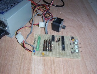 The picture shows a testing for an ink jet printer motor that is a 4-wired bipolar stepper motor. The motor has no information is povided, but traces of the printer circuit estimates the motor to be about 12V. The coil's resistance is about 4.5 ohms as it is being tested in 12V power supply in bipolar drivers. Many of the stepper motors used in printers are in 24V supply and a 7.5 degree/step. 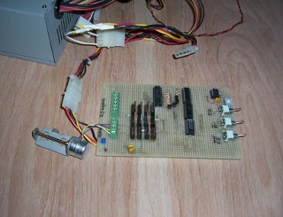 Testing a 3.5" floppy drive motor. It is a 5V bipolar stepper motor. |